CivilTech Studio
RC Shear Wall & Core Design Calculator
In-plane axial + bending (P–M interaction), in-plane shear and special boundary elements — to IS 456 + IS 13920, ACI 318 and Eurocode 2.
- In-plane P–M interaction diagram
- True-capacity flexural gate
- In-plane shear with the Vmax cap
- Boundary elements decided for you
- IS 13920:2016 Cl. 10
- IS 13920:2016 Cl. 10.4
- IS 456:2000 Cl. 32 / 39.5 / 40
- ACI 318-19 §18.10
- EN 1992-1-1 §6 / EN 1998-1 §5.4.3.4
What it does
Everything the check needs, in one pass
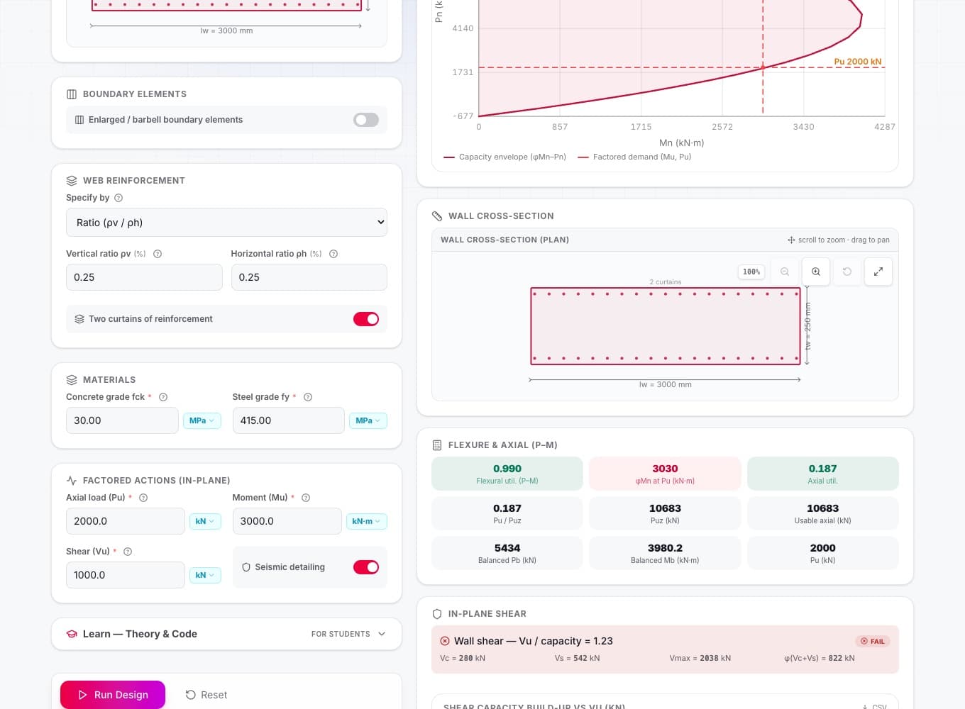
A free online reinforced-concrete shear-wall and core design calculator for practising structural engineers and students. Enter the wall section (length lw, thickness tw, boundary elements), the distributed and boundary reinforcement, and the factored in-plane actions (Pu, Mu, Vu); the tool treats the wall as a column-like section, builds the P–M interaction diagram by strain compatibility, plots your demand point against the envelope, checks the in-plane shear (Vc + Vs ≤ Vmax) and the special-boundary-element stress trigger, and verifies the minimum distributed reinforcement and two-curtain detailing.
In-plane P–M interaction diagram
The full axial-load / in-plane-moment envelope is built by strain compatibility from the distributed web steel plus boundary bars, with your factored demand overlaid — green inside the envelope, red outside.
True-capacity flexural gate
φMn at the actual Pu is read straight off the interaction curve and asserted ≥ Mu, and an axial overload (Pu beyond the squash / φ·0.80·P0 cap) is flagged as a hard fail — not an approximate closed-form.
In-plane shear with the Vmax cap
Concrete Vc, horizontal-steel Vs and the absolute shear cap Vmax are reported with the utilization, so you see whether to add horizontal steel or thicken the wall.
Boundary elements decided for you
The extreme-fibre stress trigger (σ vs 0.2·fck) tells you when special boundary elements are required, and the confinement Ash and link spacing of any provided element are checked.
How it works
From inputs to a signed-off result
- Step 1
Define the wall & boundary elements
Enter the wall length lw, thickness tw, cover and height hw; optionally toggle enlarged / barbell boundary elements and give their length, thickness, bars and confining links.
- Step 2
Set the reinforcement
Specify the distributed vertical (ρv) and horizontal (ρh) web reinforcement as a ratio or as bars at a spacing, choose one or two curtains, then the concrete grade fck and steel grade fy.
- Step 3
Enter the factored in-plane actions
Axial load Pu, in-plane moment Mu and in-plane shear Vu, plus a seismic toggle that switches on the IS 13920 / §18.10 / EC8 detailing and the boundary-element trigger.
- Step 4
Run and read the design
The engine returns the P–M curve and your demand point, the flexural / axial / shear utilizations, the boundary-element verdict with confinement, and the minimum-reinforcement checks — then export a code-referenced PDF or Excel.
Standards
Checked against the code, clause by clause
Every result cites the clause it came from, so a reviewer can follow the same path you did.
IS 13920:2016 Cl. 10
Ductile RC walls — 0.25 % reinforcement each way, spacing min(lw/5, 3·tw, 450 mm) and the in-plane shear cap τcw,max = 0.62·√fck (Cl 10.2.2).
IS 13920:2016 Cl. 10.4
Special boundary elements — required when the extreme-fibre compressive stress σ > 0.2·fck, discontinued below 0.15·fck, with confinement steel Ash.
IS 456:2000 Cl. 32 / 39.5 / 40
Wall minimum reinforcement, strain-compatibility axial-flexure (Annex G) and in-plane shear (τc enhanced by axial compression plus horizontal-steel Vs).
ACI 318-19 §18.10
Special structural walls — Vn = Acv(αc·λ·√f′c + ρt·fy) ≤ 0.83√f′c·Acv, the σ > 0.2·f′c boundary-element trigger and confinement Ash = 0.09·s·hc·f′c/fyt.
EN 1992-1-1 §6 / EN 1998-1 §5.4.3.4
Cross-section axial-flexure and shear (VRd,c, VRd,s ≤ VRd,max) with EC8 confined boundary elements over the critical height.
Who it’s for
Where engineers reach for it
Lift / stair core walls
Slender RC core walls carrying gravity plus lateral (wind / seismic) load — check the in-plane P–M demand and confirm the distributed two-curtain reinforcement.
Lateral shear walls in tall buildings
Planar shear walls resisting storey shear and overturning moment — verify the in-plane shear against the Vmax cap and whether special boundary elements are triggered.
Barbell / flanged walls with boundary elements
Walls with enlarged ends or boundary columns — model the concentrated boundary bars and confirm the confinement Ash and link spacing where σ > 0.2·fck.
Seismic ductile-wall detailing
Toggle seismic to apply IS 13920 Cl 10 / ACI §18.10 / EC8 — minimum 0.25 % each way, spacing limits and the boundary-element stress trigger.
FAQ
Questions, answered
Something else? Open RC Shear Wall / Core Designer and try it with your own numbers.
How is a shear wall designed for in-plane bending and axial load?
A slender wall is treated like a column section: the distributed vertical web steel (both curtains) and the concentrated boundary bars are discretised into fibre layers across the wall length lw, and the P–M interaction envelope is built by strain compatibility about the strong axis with the wall thickness tw as the width. The wall is adequate when the factored demand point (Mu, Pu) plots inside the curve and φMn at the actual Pu is at least Mu.
When are special boundary elements required?
Special boundary elements are required (a seismic requirement) when the extreme-fibre compressive stress under factored loads, σ = Pu/Ag + Mu·c/Ig with c = lw/2, exceeds 0.2·fck (IS 13920 Cl 10.4.1 / ACI 318-19 §18.10.6.2). They may be discontinued up the wall where the stress drops below 0.15·fck. The tool reports σ, both limits and whether any provided boundary element is adequately confined.
How is the in-plane shear capacity worked out?
The concrete contribution Vc is taken per code (enhanced by axial compression for IS 456, or αc·λ·√f′c·Acv for ACI), the horizontal web steel adds Vs, and the total is capped by the absolute maximum nominal shear (τcw,max = 0.62·√fck·tw·d to IS 13920, 0.83·√f′c·Acv to ACI). When the demand exceeds the cap, adding horizontal steel does not help and the wall must be thickened.
What minimum reinforcement does a shear wall need?
Seismic walls need at least 0.25 % distributed reinforcement in each direction (IS 13920 Cl 10.1.4 / ACI §18.10.2.1 / EC8), with the bar spacing limited to min(lw/5, 3·tw, 450 mm) and two curtains when the thickness exceeds 200 mm or the shear is high. Non-seismic walls follow the lower IS 456 Cl 32.5 / ACI §11.6 / EC2 §9.6 minima. The tool checks ρv and ρh against the governing minimum.
Which design codes are supported?
IS 456:2000 with IS 13920:2016 (seismic), ACI 318-19 including §18.10 for special structural walls, and Eurocode 2 (EN 1992-1-1) with EN 1998-1 (EC8). Pick the code with the pill selector; the interaction, shear, boundary-element and detailing checks and their clause references update accordingly.
Is the shear-wall design calculator free?
Yes — the core calculator, including the in-plane P–M interaction diagram and all code checks, is free with no card required. Optional upgrades cover advanced exports and team features.
Open RC Shear Wall / Core Designer and run your numbers
In-plane axial + bending (P–M interaction), in-plane shear and special boundary elements — to IS 456 + IS 13920, ACI 318 and Eurocode 2.
Get 10 free credits — no card required
Sign up to save projects, export PDFs, and access all design tools.