CivilTech Studio
Cantilever Retaining Wall Designer
RC retaining wall design with Rankine/Coulomb/Mononobe-Okabe earth pressure and limit-state member design — IS 14458, IS 456.
- Rankine, Coulomb and Mononobe-Okabe in one tool
- Three-member RC design
- Stability + member checks unified
- Live parametric cross-section
- IS 14458:1998
- IS 456:2000
- Rankine / Coulomb theory
- Mononobe-Okabe
What it does
Everything the check needs, in one pass
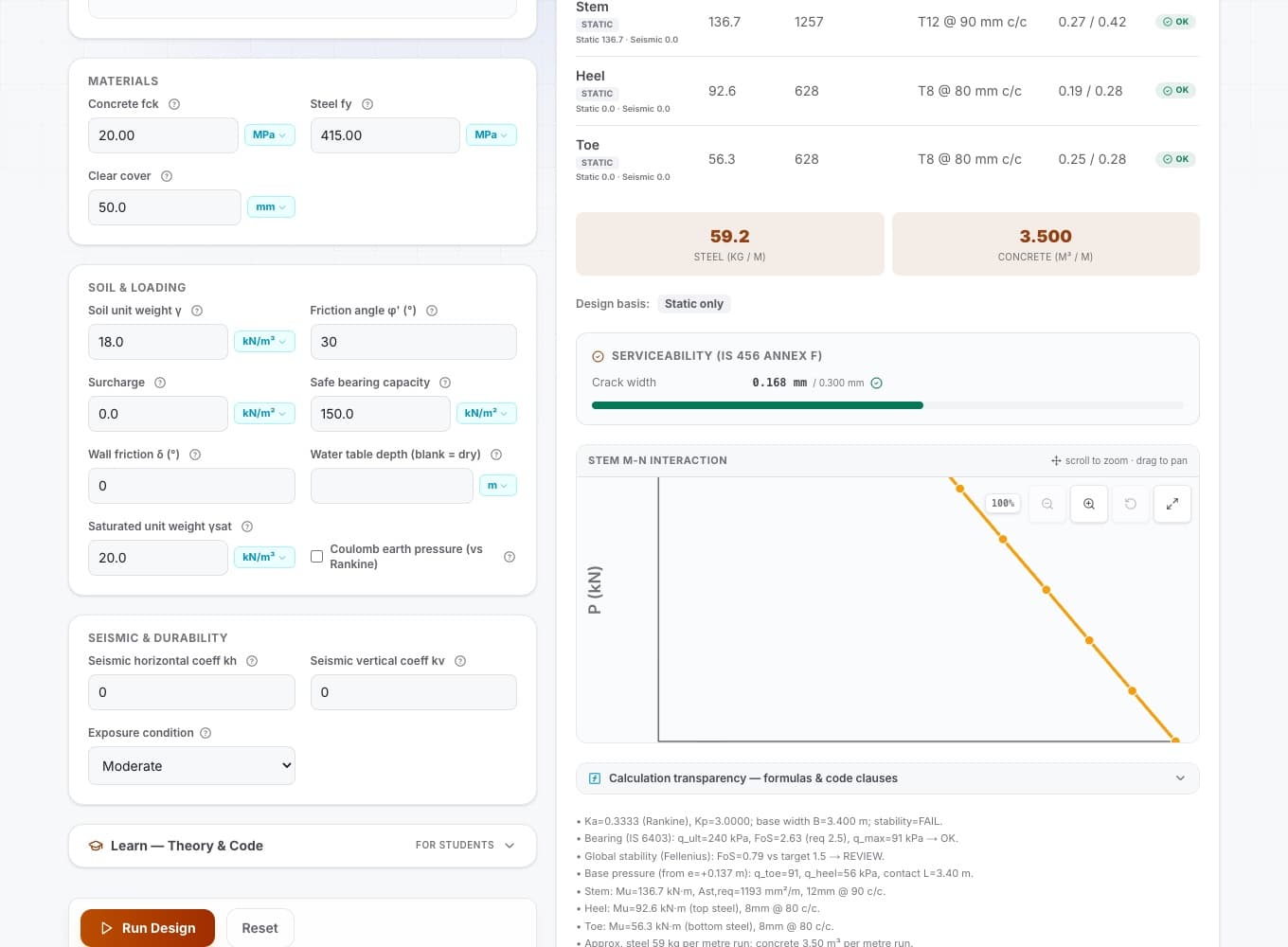
Design a cantilever reinforced-concrete retaining wall from soil to steel in one workflow. Enter retained height, wall geometry, soil friction and surcharge; get active/passive earth pressure coefficients, global stability (overturning, sliding, bearing), and member-by-member RC design (stem flexure and shear, heel and toe slab reinforcement) with a code-compliant PDF report and material take-off.
Rankine, Coulomb and Mononobe-Okabe in one tool
Toggle between earth-pressure theories without recalculating — essential for comparing passive resistance and wall-friction effects.
Three-member RC design
Stem, heel slab and toe slab are sized and reinforced together — moment and shear in each determined from factored earth and base pressures.
Stability + member checks unified
Global overturning, sliding and bearing (with eccentricity) are reported alongside flexure, shear and reinforcement — one design file, no handoff.
Live parametric cross-section
As you edit height, thickness and projections, a schematic redraws to show retained soil, base pressure distribution, and active-pressure triangle.
Bar bending and material quantify
Reinforcement is assigned by diameter and spacing to IS 456 rules; steel and concrete per metre run are summed for procurement.
How it works
From inputs to a signed-off result
- Step 1
Enter wall geometry and soil
Retained height, stem thickness, base slab thickness, toe/heel projections, soil unit weight, friction angle, surcharge and safe bearing capacity.
- Step 2
Choose earth-pressure theory
Rankine (classic, no wall friction) or Coulomb (with friction angle) — coefficients Ka and Kp are displayed alongside global stability factors.
- Step 3
Review stability and element design
Overturning and sliding factors of safety, base bearing pressure, and per-member moment/shear demands with required and provided flexural steel.
- Step 4
Export PDF report and material schedule
A stamped report includes all inputs, stability checks, reinforcement detail (bar size and spacing for stem, heel, toe) and a take-off of steel and concrete per metre.
Standards
Checked against the code, clause by clause
Every result cites the clause it came from, so a reviewer can follow the same path you did.
IS 14458:1998
Code of practice for design, construction and installation of cantilever retaining walls
IS 456:2000
Code for plain and reinforced concrete — limit-state flexure, shear, minimum steel distribution
Rankine / Coulomb theory
Active and passive earth pressure coefficients — classical and with wall friction angle
Mononobe-Okabe
Seismic earth pressure — for dynamic conditions
Who it’s for
Where engineers reach for it
Residential plot-line boundary wall
3–5 m height with zero toe (flush with boundary) — the tool sizes heel only and checks whether wall friction can be relied on.
Industrial compound or parking perimeter
Taller walls (6–8 m) with traffic surcharge; compare Rankine vs Coulomb to see if soil-friction edge support saves concrete.
Basement retaining wall with surcharge
Multi-level building surcharge on backfill — Coulomb with wall friction models the pinned-base condition; heel and toe slab design handles the combined dead load and earth pressure.
Quick estimate for scheme design
Input nominal soil bearing capacity and friction angle to size the wall before detailed geotechnical investigation — refine dimensions once SBC is confirmed.
FAQ
Questions, answered
Something else? Open Retaining Wall Designer and try it with your own numbers.
Which IS code does it follow for cantilever wall design?
IS 14458:1998 for cantilever retaining wall practice, with member-level flexure and shear checks per IS 456:2000 limit-state method. Design is to ultimate limit state (factored loads); global stability uses service-level (unfactored) pressures.
What is the difference between Rankine and Coulomb earth pressure?
Rankine assumes a smooth wall (no friction); it is quicker and conservative. Coulomb accounts for wall-soil friction (angle δ), reducing active pressure and increasing passive resistance — useful for cast-in-situ walls with roughened faces.
Does it compute factor of safety for overturning and sliding?
Yes — global stability is reported with overturning FoS (typically ≥ 2.0) and sliding FoS (typically ≥ 1.5), plus base bearing pressure and eccentricity. If either fails, wall dimensions need adjustment.
How are stem, heel and toe reinforcement designed?
Each member is treated as a cantilever: the stem resists active-earth thrust, the heel resists downward soil + surcharge load (top steel), and the toe resists upward net base pressure (bottom steel). Bar diameter and spacing are chosen per IS 456 minimum and spacing limits.
Can I run this in the browser, or does it upload my data?
It runs in the browser. Your inputs go over an encrypted connection to our calculation engine, which returns the design and keeps no copy. The design is stored in your CivilTech Studio account only if you save it. PDF reports are generated on our server and downloaded straight to you.
What output formats are available?
PDF report (stamped with codes, all checks, reinforcement detail and notes) and Excel spreadsheet (inputs, stability results, member design table and material take-off) — ready for contractor or regulator review.
Open Retaining Wall Designer and run your numbers
RC retaining wall design with Rankine/Coulomb/Mononobe-Okabe earth pressure and limit-state member design — IS 14458, IS 456.
Get 10 free credits — no card required
Sign up to save projects, export PDFs, and access all design tools.